
Draw Tool Uses
The draw tool will behave differently according to the type of layer that you have selected in the layer panel. For drawing on a transport layer, see the infrastructure drawing methods below, or for drawing on data layers, please see this dedicated page.
Infrastructure Drawing Methods
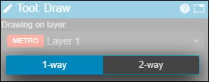
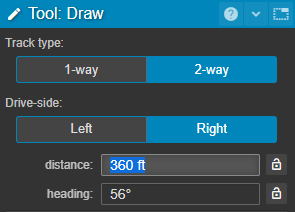
- Once you have selected the draw tool, you will be given the option of drawing one or two way paths. The default is 1-way but this can be toggled from within the Tool Properties panel, or by using the Shift+1 or Shift+2 keyboard shortcuts.
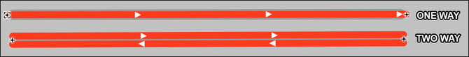
1 and 2 way paths can be distinguished visually by zooming into the map.
- The Draw tool's properties panel also allows you to set the drive-side for a 2-way path.
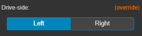
The drive-side of 2-way path is determined by the location set during the project's creation. You can toggle this setting to override the legal drive-side for the country in which your project is based. The default drive-side for the project can also be changed in the Project Settings.
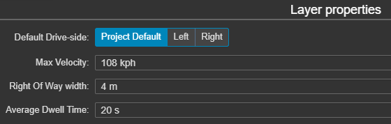
The drive-side can be set on a per-layer basis when adding a new layer, or when changing a layer's properties. Here you can select from the default specified in the Project Settings or from left/right/
-
Click once on any part of the map to add a control point.
 Connecting lines will be added automatically between additional control points. Curves will generated automatically according to the properties of the active layer's LayerType.
 -
Stations can be linked by using the draw tool to select each one in succession.
-
Clicking within an existing line will add an additional constraint point. By default, this point will be constrained to its line. It can be unconstrained by un-checking "snap to line" in its properties.
- Click-dragging on a line will insert a new point not snapped to that line. You can then move the point to any location.
![]() Note: constraint points can only be added to straight control lines and not paths (curved lines) generated by the application
Note: constraint points can only be added to straight control lines and not paths (curved lines) generated by the application
With the draw tool (as with the Select tool), you may also select and move individual points, by dragging them around.
Note that depending on the Layer Type of the current layer, you may not always be able to connect two points together. (For example: Personal Rapid Transit systems only allow merges and diverges with a maximum of two inbound or two outbound connections.)
Precise Drawing
It is possible to define the exact dimension of a line if you require greater accuracy than is achievable by drawing freehand.
-
Select the draw tool and either select an existing control point by clicking on it, or click on the map to create a new control point.
-
Extend the guideline so that it is pointing in the desired direction.
-
Type a dimension -- followed by the desired units: "m", "km", "ft", or "mi" -- and type Enter to create a line of that distance.
-
Typing a dimension and pressing Tab will allow you to enter the heading in degrees. 0 is north, 90 is east, 180 is south, 270 or -90 is west.
-
Pressing Enter or Tab again will complete the line.
This process allows you to specify very exact dimensions. If, for example, you wanted to draw a line 100m due north, then 50m north-east, you would first click to begin drawing the line, then:
- Type 100m Tab 0 Enter to draw the line due north.
- Type 50m Tab 45 Enter to draw the line northeast.
The ![]() button will lock either the distance or heading setting, allowing you to move the other freely.
button will lock either the distance or heading setting, allowing you to move the other freely.
![]() Note: Precise drawing is currently only available for transport layers (this feature is coming soon for dataset layers).
Note: Precise drawing is currently only available for transport layers (this feature is coming soon for dataset layers).
Understanding parametric constraints
The Draw tool generates curves with constraints-based parametric modelling, which unifies planning and engineering concerns. It applies the following rules, in order of priority:
- All curves must be tangent to their defining lines
- The path must be as fast as possible (since transport planners generally want speed)
- The path must be as straight as possible (since curves are more expensive to engineer)
Often, these automatic curves are exactly what you want. When they're not, you can make different curves by setting selecting their points and setting additional constraints, as in the video above.
Creating complex geometry with 2-way paths
The ability to mix 1 and 2 way paths makes the creation of complex transport systems such as roundabouts and cloverleaf junctions easy. The video below demonstrates just how quick the process can be.
Drawing Data Layers
The draw tool can also be used to draw data geometry on dataset layers. For more information, please see this page on creating dataset layers.